Introduction
This collection of materials was collected and written for a two day university workshop with (more or less) absolute beginners in mind.
The goal is to convery the very foundations of (DIY) electronics and how they relate to physical computing as an artistic tool and skill.
That being said, there is only so much one can cover in two days. So this is far from a comprehensive guide but, as the title suggests, an introduction to the field.
Big thanks to Stefan Püst for the original workshop and materials!
Build
Created using mdbook. To build it yourself run (assuming Rust toolchain installed)
$ cargo install mdbook
$ mdbook build
Then serve the output statically.
License
Intro to Physical Computing © 2024 by lislis is licensed under CC BY-SA 4.0
What is Physical Computing?
-
Where the physical world interfaces with computing.
-
Expanding input though sensors.
-> More than touch interfaces and keyboard/mouse.
-
Expanding output through actuators.
-> More than displays.
Inputs & Outputs
Inputs - sensors
- Components that sense properties of the physical world
-
Different ways to convert physical properties into electrical signals
-
Light
-
Simple/ complex touch
-
Temperature
-
Magnetism
-
Sound
-
simple / complex pictures
-
-
Wide variety of sensors
-
simple to complex
-
cheap to expensive
-
Outputs - actuators
- Components that change properties in the physical world
-
Different conversions of electrical signals into physical properties
-
Light
-
Sound
-
Displays
-
Motion
-
Signals
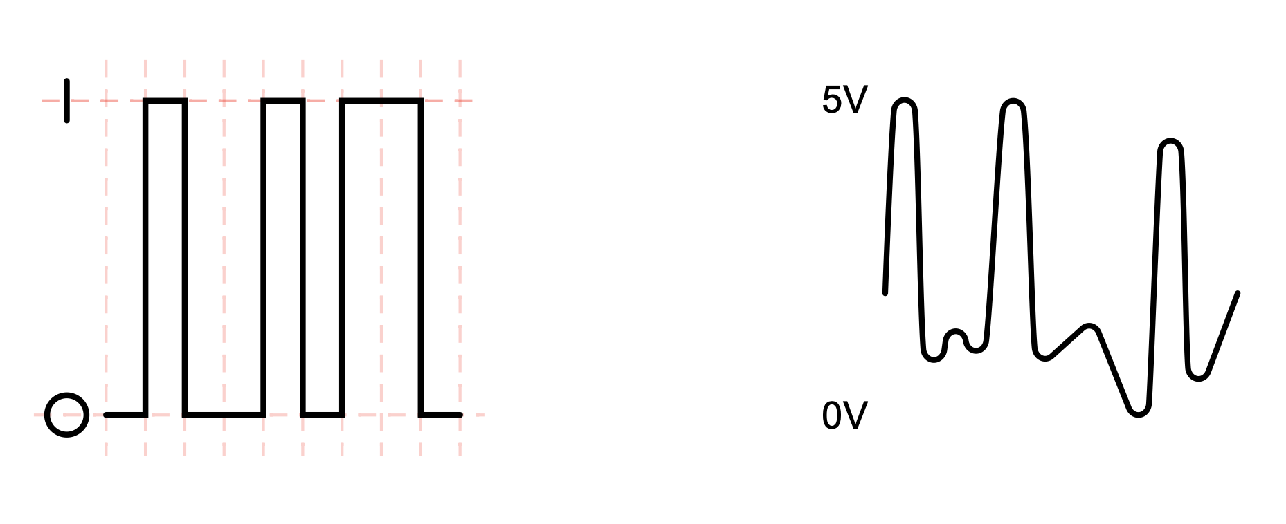
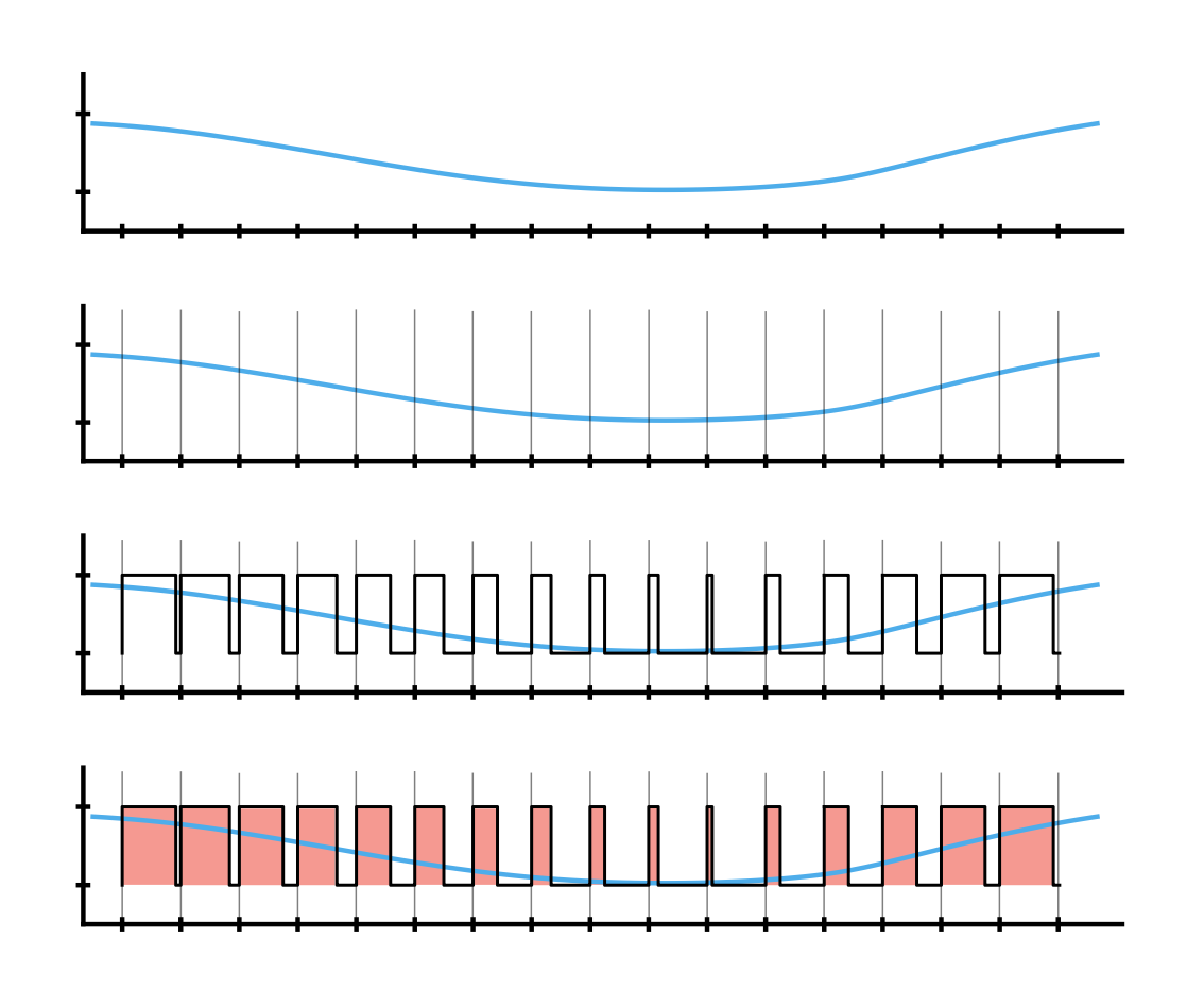
Digital vs Analog
-
Analog signals are continuous with infinitely smooth transitions
-
Digital signals are fixed “steps” with a set resolution
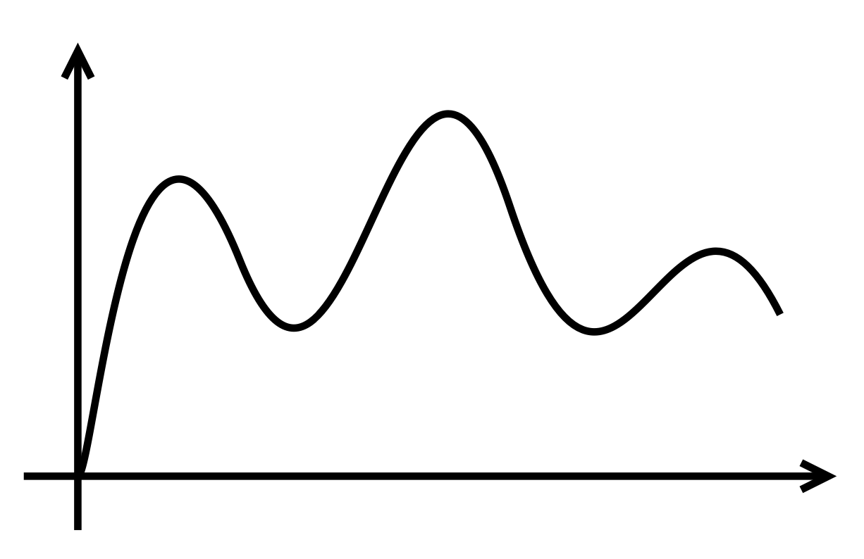
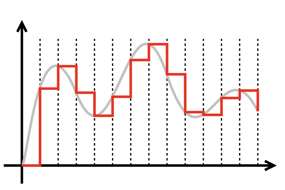
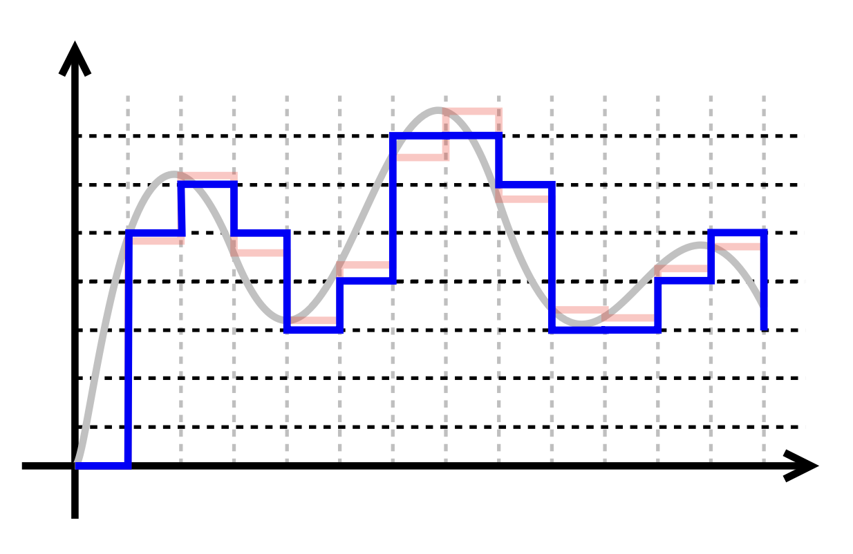
Conversions
- From an analog signal we sample at given rate and quantise with a given depth.
- From digital to analog we can only approximate through Pulse-Width-Modulation
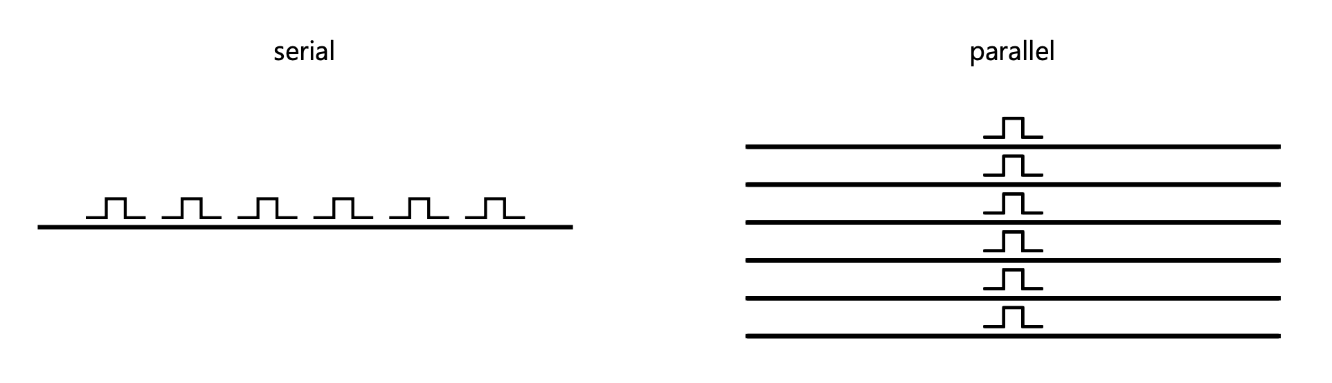
Parallel vs Serial
- When we send signals we can send them in parallel or in serial
Computers
-
Brain of Physical Computing project
-
Comes in different sizes
-
Converts input to outputs
-
Must be programmable
-
Digital device
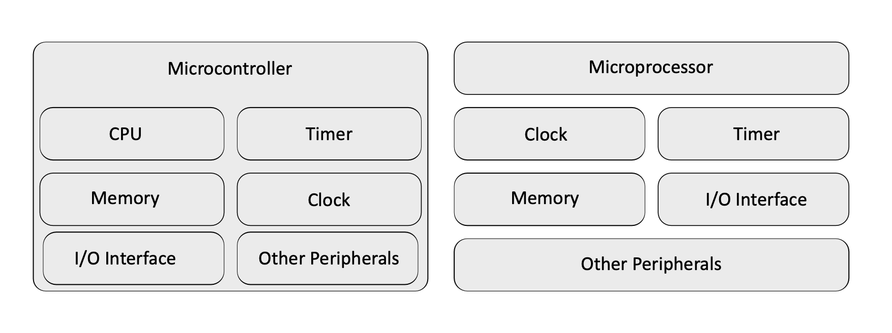
Microcontrollers
-
Very application specific
-
Run one program
-
Usually very cheap
-
Low technical specs
-
Periphery (RAM, IO) included
-
Are in bascially everything

Microprocessors
-
Basically a computer
-
Needs periphery (RAM, memory)
-
Runs an operating system

Comparison
Why these?
-
Widespread platforms, lots of documentation
-
Inexpensive
-
Optimized for hobbyists and learners
-
Software-libraries for nearly everything, big open source ecosystem
Arduino Platform
“Arduino” can mean different things:
- microcontroller development board
- software framework
- IDE
Boards
There is a wide variety of boards available from Arduino directly. Since everything is open hardware there are also a lot of (compatible, cheaper) copy-cats and variations for different purposes.
Need a little more powerful hardware? Maybe a Teensy is right for you. Which in turn is the base for the Daisy.
Into wearables and sewing projects? Maybe the Lilypad is for you.
For interfacing with wifi or bluetooth I recommend an ESP32 or the sightly older (and cheaper) ESP8266.
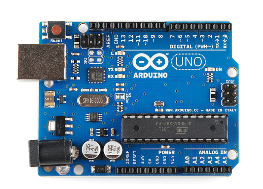
The absolute go-to for beginners and prototyping is the Arduino Uno.
Arduino Uno
- ATmega328P microcontroller (watch out when buying very cheap boards!)
- 8 Bit architecture 16 Mhz
- 2 KB RAM
- 1 KB ROM
- 32 KB Flash Memory
- 14 digital IO pins with 6 PWM pins
- 6 analog input pins with 10 bit analog-digital-converter
IDE
IDE 1.x was based on the Processing IDE.
IDE 2.x is a rewrite using VS Code/ Electron which was … a choice, but it’s the new standard so we’ll roll with it.
Download the Arduino IDE 2.x here.
Within the IDE you’ll program arduino-flavoured C++, which you should already be (somewhat) familiar with.
Raspberry Pi
In this workshop we will not be talking Raspberry PIs specifically.
But if you want to you can ask for followup workshops.
Tech specs
- ARM processor like in you smartphone
- Different RAM-size models
- Integrated GPU
- Many periphery components (IO Pins, USB, HDMI, LAN, WLAN, Bluetooth)
- SD-card as mass-storage
Software
- Linux-based
- With or without graphical desktop (headless)
- Programming in every language that is available for Linux
- You’re basically managing a server
Electricity & Circuits
Since we’ll get in touch with the physical world, we need to learn about some physical properties of the world, and how they relate to each other.
With this knowledge we can start working on circuits, which I sometimes think of as programming in hardware.
After that we can start reading values from our circuit via a microcontroller.
Electricity
Electrical charge
| Symbol | Unit |
|---|---|
| Q | Coulomb (C) or Ampere Second (As) |
-
Physical property on which all electricity is based
-
Bound to matter, needs a charge carrier (e.g. electrons)
-
Positive, negative, neutral charge
-
Different charges attract, similiar charges retract
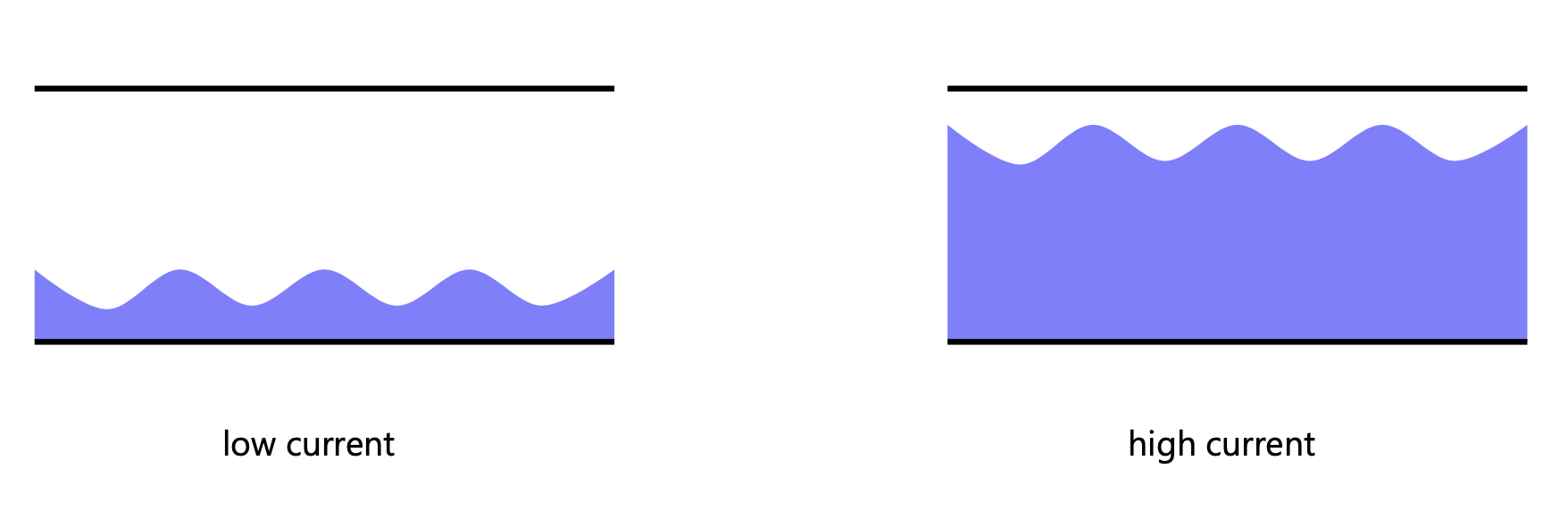
Electrical current
| Symbol | Unit |
|---|---|
| I | Ampere (A) |
-
Result of moving charge carriers
-
The more charged particles move between conductors, the more current flows
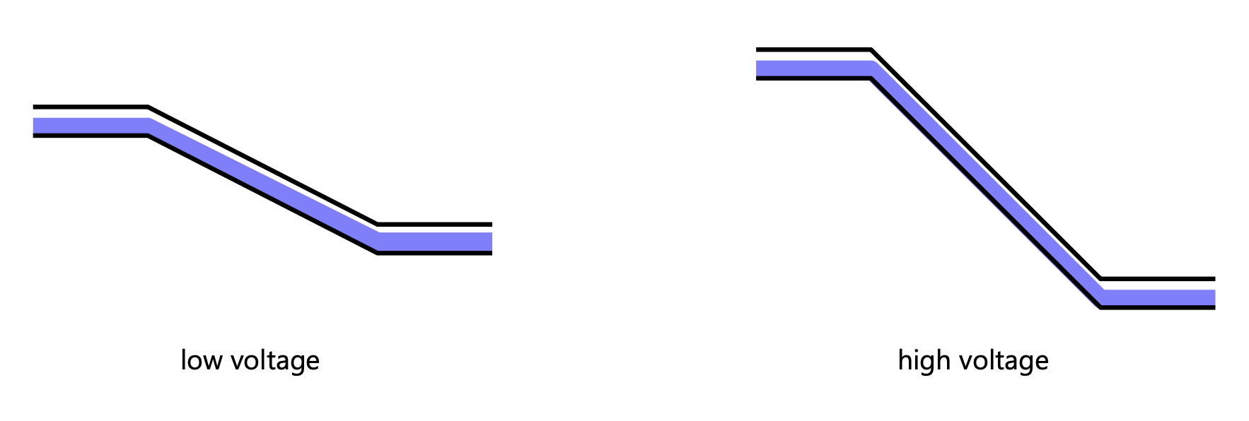
Electrical voltage
| Symbol | Unit |
|---|---|
| U | Volt (V) |
-
Causes the movement of charge carriers
-
Difference of potential
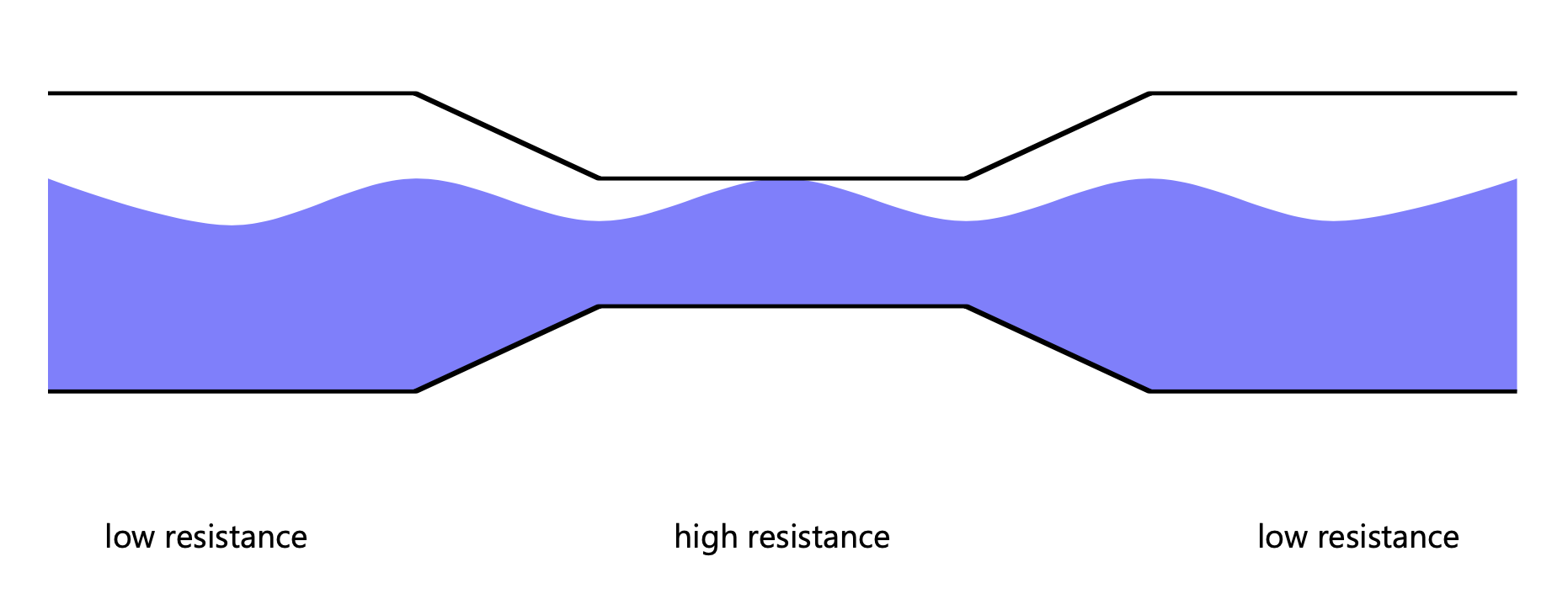
Electrical resistance
| Symbol | Unit |
|---|---|
| R | Ohm (Ω) |
-
Caused by obstruction of charge carriers in conductors
-
Converts electrical energy into heat
Capacitance
| Symbol | Unit |
|---|---|
| C | Farad (F) |
-
Ability to store electric charge
-
Measured as
charge / voltage
Electrical power
| Symbol | Unit |
|---|---|
| P | Watt (W) |
-
Amount of energy per time unit t
-
W = I x U
Water model
Measuring
We measure current flowing through one point.
We meassure voltage between two points.
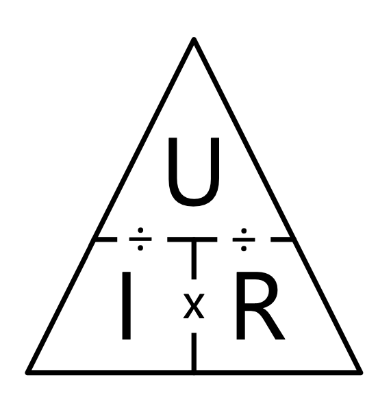
Ohm’s Law
- Describes the relationship between voltage, current and resistance
Kirchoff’s Law
Current Law
-
The sum of all current flowing into and out of a joint is 0
-
What goes in goes out (like in a crossing of water pipes)
-
Current that flows in has a positive sign, current that flow out has a negative sign
Voltage Law
-
The sum of all voltages in a loop is 0
-
Is a consequence of the rule of “conservation of energy” (energy can not be created neither disappear in closed system)
Consequences
In a parallel circuit voltage (U) stays the same, currents need to be summed up
In a serial circuit current (I) stays the same, voltages need to be summed up
Good news
In the beginning, you don’t really have to care about these things too much.
It will only become relevant once you start building larger, more complex circuits, and then you can find the formulas and plenty of other resources online.
Parts & components
The computational unit is not enough for a physical computing project, we need some other hardware components as well.
Components
Let’s build a circuit!
What do we need?
Minimum equipment
Arduino
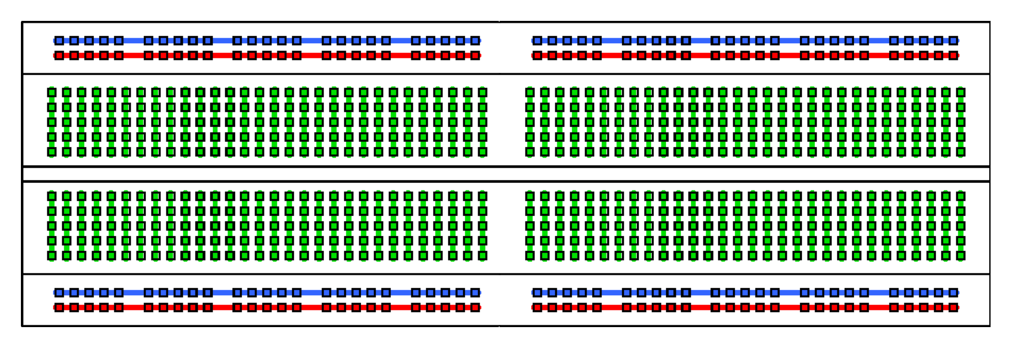
Breadboard
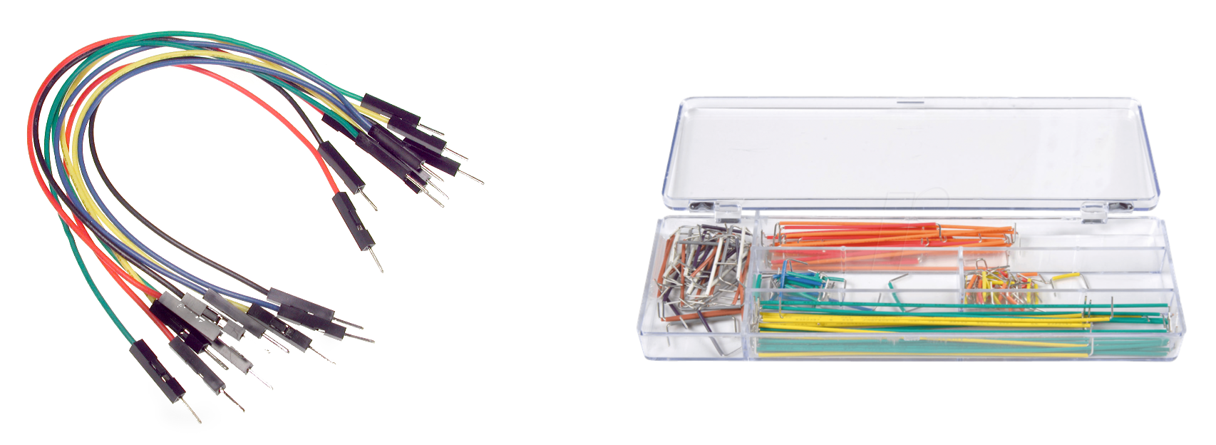
Wires
Components
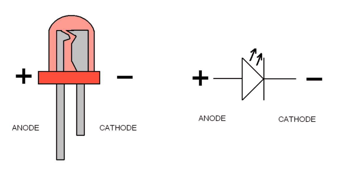
LEDs
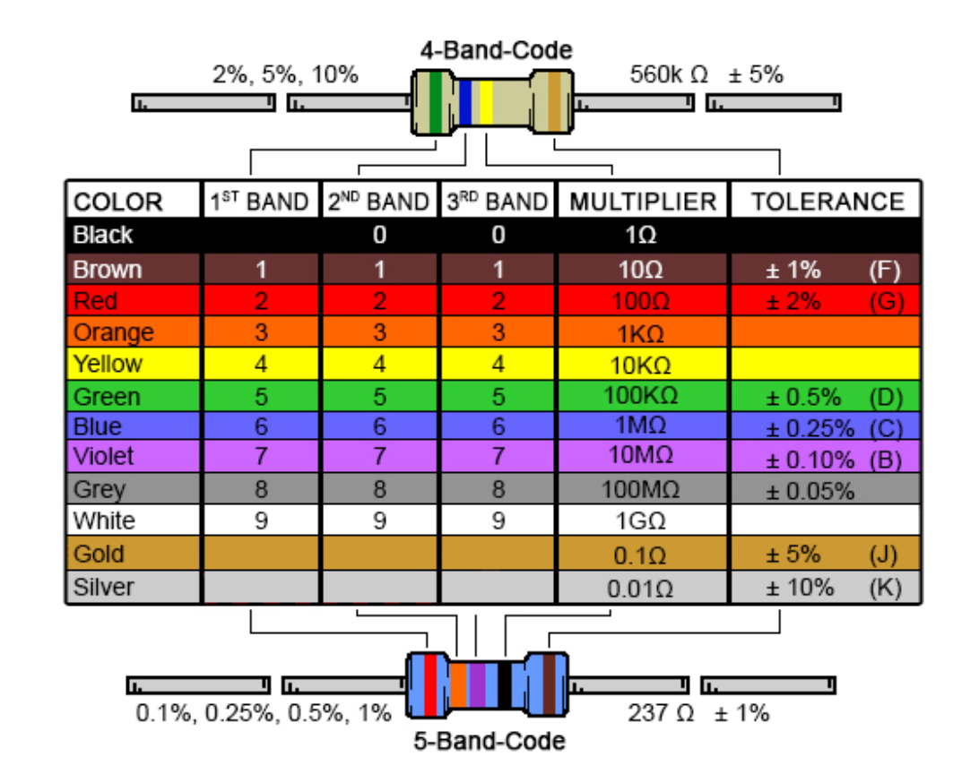
Resistors

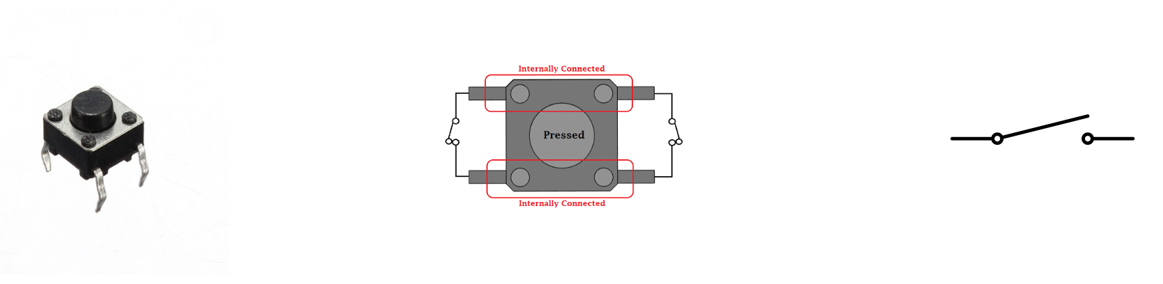
Buttons
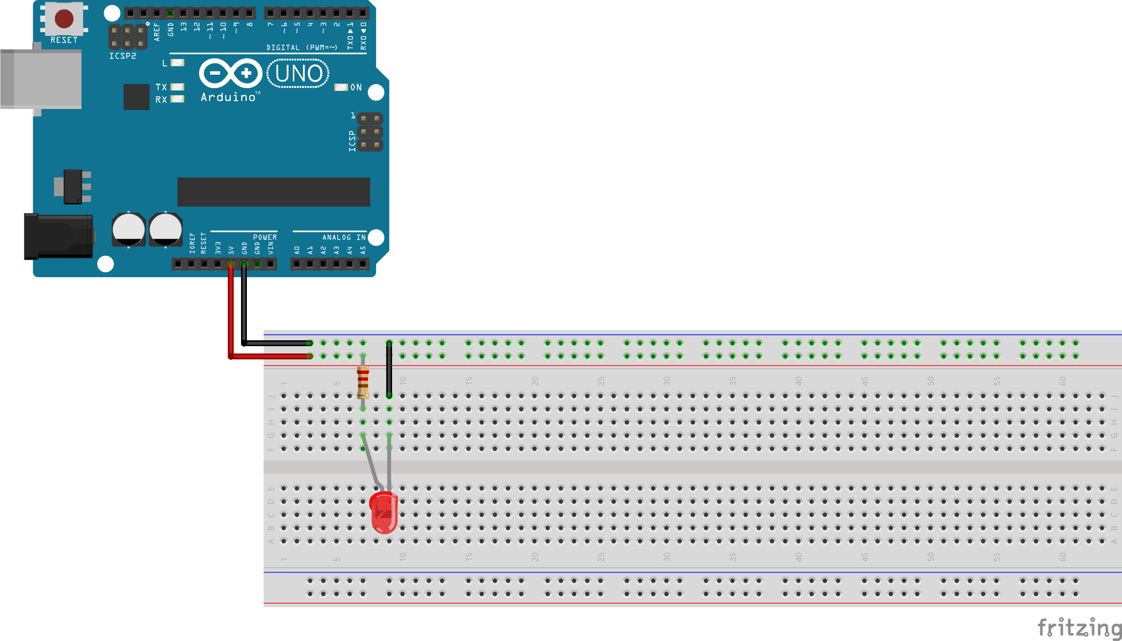
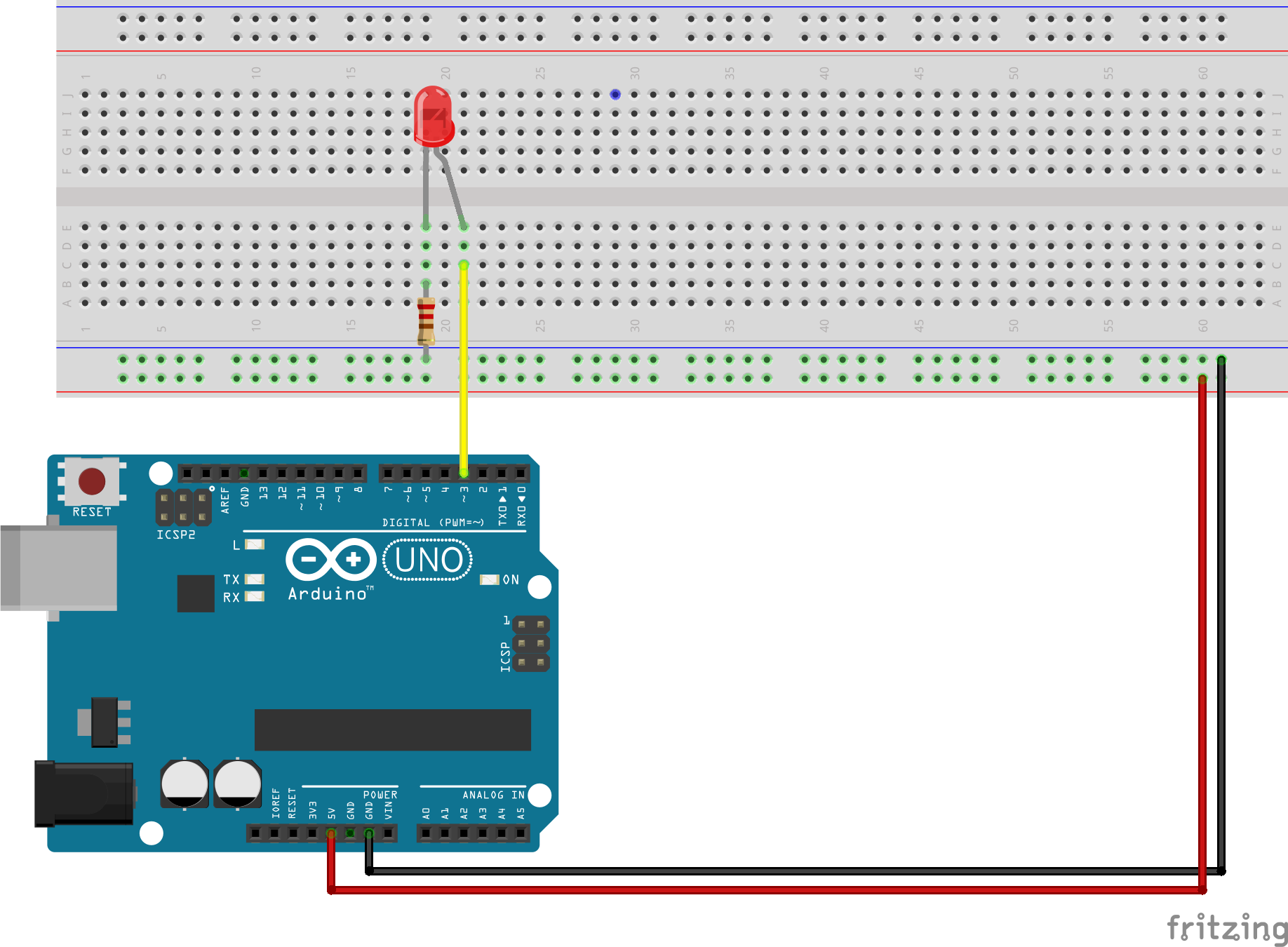
Circuit 1.1: Light up an LED
We will use the Arduino just as a power source and not program it yet.
Try to replicate this circuit on your breadboards:
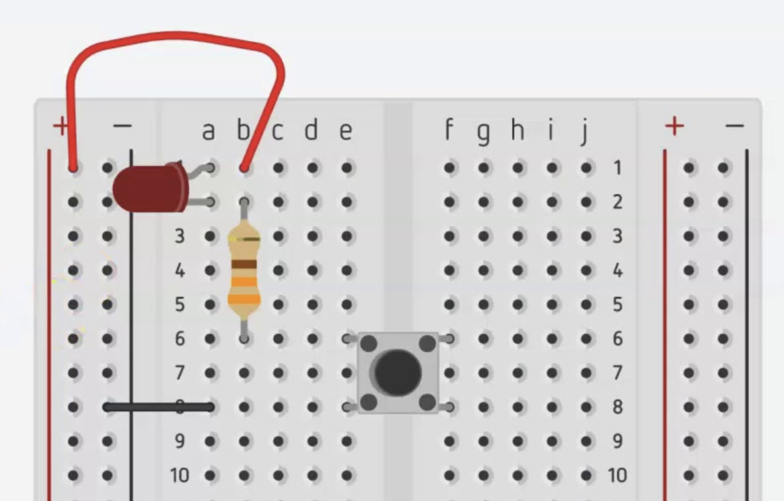
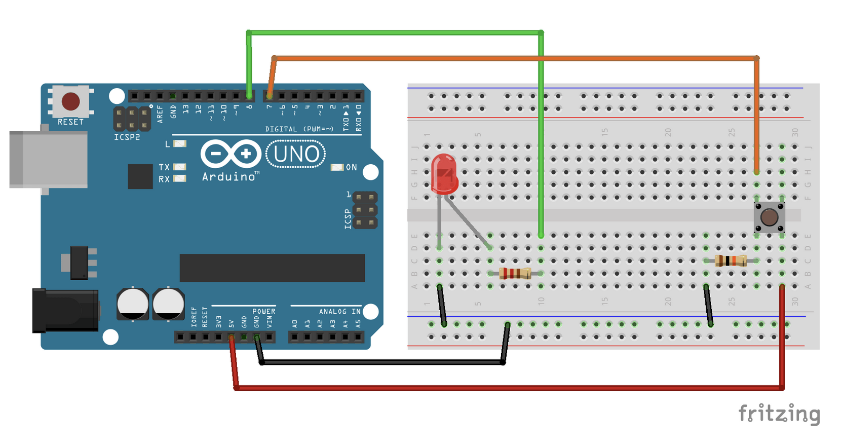
Circuit 1.2: Light up LED on button press
Let’s add a button to turn the LED on and off.
Try to replicate this circuit on your breadboards:
Arduino & Arduino IDE
If you haven’t already download the Arduino IDE 2.x here.
We will do all programming in the IDE as it will take over the task of compiling and flashing the code on the board for us. Convenient!
Circuit 1.3: Hello, blinky World!
Making an LED blink is the hardware-equivalent of printing “Hello, Word!”.
Change your circuit to this:
Add this code, save and upload it to your Arduino:
void setup() {
    pinMode(3, OUTPUT);
}

void loop() {
    digitalWrite(3, HIGH);
    delay(1000);
    digitalWrite(3, LOW);
    delay(1000);
}
It’s nicer to put your pins into variables at the top.
#define LED_PIN 3
// or int led_pin = 3;

void setup() {
    pinMode(LED_PIN, OUTPUT);
}

void loop() {
    digitalWrite(LED_PIN, HIGH);
    delay(1000);
    digitalWrite(LED_PIN, LOW);
    delay(1000);
}
Circuit 1.4: Programmed Button
Let’s add the button back to the mix.
This time we will read the button state via the Arduino and then use it to make the LED light up.
Change the circuit to this:
This is the code:
int led_pin = 3;
int button_pin = 4;
bool button_state = false;

void setup() {
  pinMode(led_pin, OUTPUT);
  pinMode(button_pin, INPUT);
}

void loop() {
  button_state = digitalRead(button_pin);
  digitalWrite(led_pin, button_state);
}
Pulldown resistor
Why does the button need a resistor? Good question!
-
When the button is in an open state it there is no defined value on its pin but the Arduino will still try to read it
-
In this case the open button behaves like an antenna and catches electrical charge around it (Sometimes that’s what you want, see EMF/Ghost detector)
-
Try removing the resistor and look at the difference!
-
The Arduino comes with an internal resistor for this exact case, search for
pinMode(pin, INPUT_PULLUP)
Circuit 1.5 Cycle through LEDs
Now let’s get a bit more fancy with the programming.
We’ll create a circuit with four LEDs in parallel, but only one LED will light up at a time. With the press of the button we will cycle through the LEDs, so that they light up one after the other.
This is actually quite complex! Let’s build up to it with a couple of steps!
Circuit with four LEDs and a button
Change the circuit so that you have four LEDs and each one is connected to a different pin on the Arduino. Don’t forget the resistors!
To test if things are wired correctly you can write some code to light all LEDs up when the button is pressed. (Basically what we had before)
int ledPin1 = 2;
int ledPin2 = 3;
int ledPin3 = 4;
int ledPin4 = 5;
int buttonPin = 12;

void setup() {
    pinMode(ledPin1, OUTPUT);
    pinMode(ledPin2, OUTPUT);
    pinMode(ledPin3, OUTPUT);
    pinMode(ledPin4, OUTPUT);
    pinMode(buttonPin, INPUT);
}

void loop() {
  buttonState = digitalRead(buttonPin);
  digitalWrite(ledPin1, buttonState);
  digitalWrite(ledPin2, buttonState);
  digitalWrite(ledPin3, buttonState);
  digitalWrite(ledPin4, buttonState);
}
Running lights
But we want cyclic behaviour, and there is an operant which is perfect for that!
It’s modulo, aka %, aka the remainder!
With modulo in mind, change the code so that we have a counter that counts up and is responsible to light up an LED for a second before moving on to the next.
(One possible) Solution
int ledPin1 = 2;
int ledPin2 = 3;
int ledPin3 = 4;
int ledPin4 = 5;
// int buttonPin = 12;
int counter = 0;

void setup() {
    pinMode(ledPin1, OUTPUT);
    pinMode(ledPin2, OUTPUT);
    pinMode(ledPin3, OUTPUT);
    pinMode(ledPin4, OUTPUT);
    //pinMode(buttonPin, INPUT);
}

void loop() {
  // buttonState = digitalRead(buttonPin);
  digitalWrite(ledPin1, LOW);
  digitalWrite(ledPin2, LOW);
  digitalWrite(ledPin3, LOW);
  digitalWrite(ledPin4, LOW);

  counter = (counter + 1) % 4;
  digitalWrite(counter + 1, HIGH);

  delay(1000);
}
Bring back the button
Last step, instead of running by itself, we want to change the LED via the press of the button.
To see if the button was just pressed instead of continually pressed, we need to keep track of its current state and previous state. We can do that with two boolean variables.
Solution
int ledPin1 = 2;
int ledPin2 = 3;
int ledPin3 = 4;
int ledPin4 = 5;
int buttonPin = 12;
int counter = 0;

bool buttonState = false;
bool lastButtonState = false;

void setup() {
    pinMode(ledPin1, OUTPUT);
    pinMode(ledPin2, OUTPUT);
    pinMode(ledPin3, OUTPUT);
    pinMode(ledPin4, OUTPUT);
    pinMode(buttonPin, INPUT);
}

void loop() {
  buttonState = digitalRead(buttonPin);

  digitalWrite(ledPin1, LOW);
  digitalWrite(ledPin2, LOW);
  digitalWrite(ledPin3, LOW);
  digitalWrite(ledPin4, LOW);

  if (buttonState && !lastButtonState) {
    counter = (counter + 1) % 4;
  }
  digitalWrite(counter + 1, HIGH);

  lastButtonState = buttonState;
  delay(1000);
}
Did you notice strange behaviour?
Our buttons are mechanical but we treat their state als digital signals.
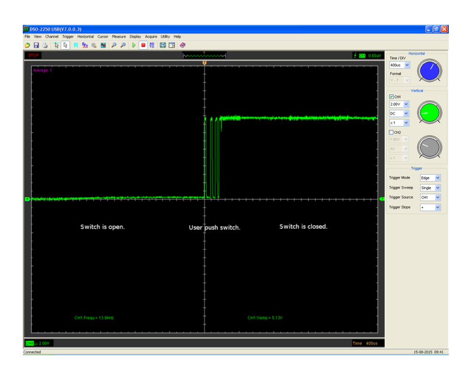
-> The physical state of the button can produce values inbetween ON and OFF that our program might interpret as either.
We can solve this programmatically by adding a short (e.g. 20ms) delay or adding a debounce timer or using bitshift logic. We can also solve this with another hardware component called capacitor.
But it’s been a long day so we will end it here :)
Just keep in mind that we are dealing with physical things and they exist outside of a computer binary!
Serial communication
Can we print to a console?
You ran into the issue of wanting to debug something by now.
We can accomplish this by using serial communication!
Talking serial
For two devices to communicate serially we have to establish a transmission rate, the so-called Baud rate.
This is typically 9600 (pulses per second) but you can also choose faster ones (eg 115200).
It’s important though that both sides use the same Baud rate!
Both sides?
We are now opening a two-way-channel between the Arduino and your computer.
The Arduino will send (or read) at the Baud rate to your computers serial communication port.
Your computer can read (or write) from that port. Right now it’s the Arduino IDE’s serial console that will do just that.
Endless possibilities
Only one program at a time can read from the serial port!
It doesn’t have to be the Arduino IDE, but it’s nice for debugging.
It can be Unreal, Unity, Touch Designer, Max/MSP, your own Node script etc.
Getting started
void setup() {
  # we have to initialize Serial in the setup
  Serial.begin(9600);
  # then we can print or println (with a line break)
  Serial.println("Done with setup entering loop");
}

void loop() {
  Serial.print("loop");
  delay(500);
}
Reading
We can also read from Serial, very useful when data comes from a program and the Arduino should act on it.
const int ledPin = 9;

void setup() {
  pinMode(ledPin, OUTPUT);
  Serial.begin(9600);
  Serial.println("Done with setup entering loop");
}

void loop() {
  String reading;

  if (Serial.available()) {
    reading = Serial.readString();
    reading.trim();
    if (reading == "on") {
      digitalWrite(ledPin, HIGH);
    } else if (reading == "off") {
      digitalWrite(ledPin, LOW);
    }
  }
}
We can .read() (bytes) or .readString() (String), depending on what data you have. Also look into documentation online!

Analog values
We read analog values (like resistance or capacitance) via the analog pins!
Classic controls such as potentiometers and faders change their resistance base on their rotation or position.
Instead of using it for purposes strictly for the circuit, we can read the change and map it to something else.
Common analog “sensors” are photoresistors (measure direct light), rain or soil moisture sensors.
It’s pretty straight forward, and basically you already know everything.
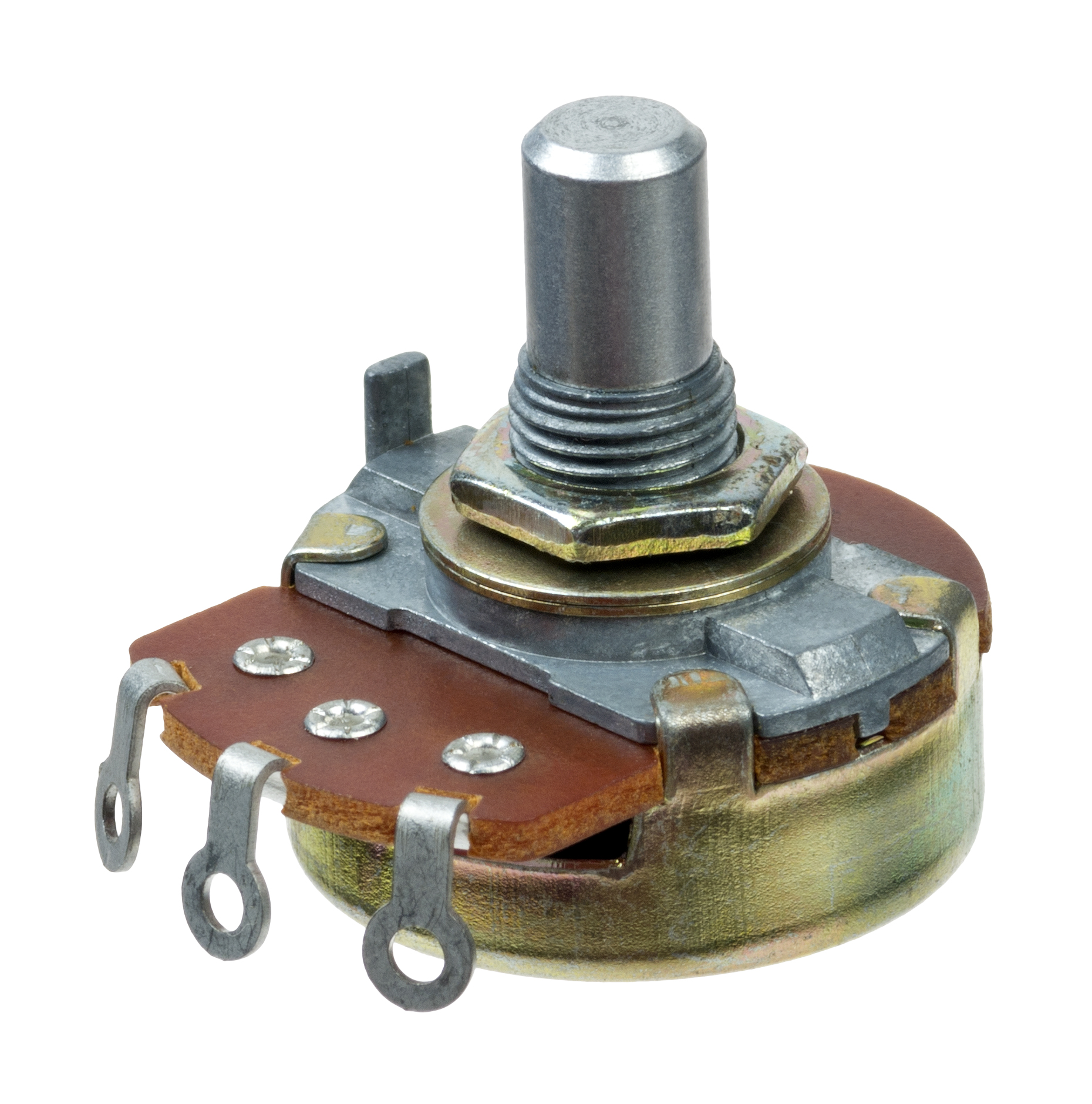
Potis don’t care about the direction of current.
They usually have three legs, the outer ones for GND and VCC, the middle one for reading.
void setup() {
    Serial.begin(9600);
    pinMode(A0, INPUT);
}

void loop() {
  # analogRead gives us values between 0 and 1023
  int reading = analogRead(A0);
  Serial.println(reading);
}
Change the VCC from 5V to 3.3V. What do you notice?
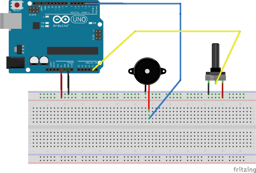
[Circuit 2.1] Beep boop
In this exercise we’ll start mapping an analog input to our first actuator, a piezzo buzzer!
It’s a speaker in its simplest form, just a membrane that vibrates when it receives an electic current.
This will make a lot of annoying sounds. Sorry about it! But it’s also fun :D
const int poti = A4;
const int buzzer = 3; // this has to be a PWM pin!

int reading, mapping;

void setup() {
    Serial.begin(9600);
    pinMode(poti, INPUT);
    pinMode(buzzer, OUTPUT);
}

void loop() {
  reading = analogRead(poti);
  Serial.println(reading);
  mapping = map(reading, 0, 1023, 200, 800);
  tone(buzzer, mapping);
}
tone is a special function in Arduino that takes a pin and a frequency. It will then modulate the states on that pin to mimic the given frequency. Attached to a membrane this will create sound! Magic!
If you’re wondering how exactly the Arduino produces the sound (it’s all PWM after all!) you can find a very in-depth description with code examples here.
You may know map from coding environments like Processing, it’s also called map_range sometimes.
In this case it has nothing to do with the ‘functional-style’ map that you may know from map, filter, reduce.
Our map interpolates the first argument, originating from a range defined by arguments two and three, into a new range defined by arguments four and 5.
We just map the analog values from out poti to a range of frequencies, which arguably doesn’t sound pleasant.
As an exercise, look up frequencies from actual notes and think of a different kind of mapping.
You could for example map to a range from 0 - 8 (scale size) and then look up the appropriate notes from an array using the mapping as index.
Sensors
Sensors come for almost anything at this point.
Most of the time they make use of the same physical properties we talked about and see how they change under different circumstances.
Analog vs Digital
The Arduino Uno has analog and digital pins for connecting the respective kinds of sources.
If you end up working with a different micro-controller, make sure to check the datasheet/ pinout to see if/which pins can be used for analog signals!
What’s the difference in reading?
Analog input is represented with in a value range from 0 to 1023 (for the Uno!).
Digital is represented as true/ false, HIGH/LOW.
But digital can do more!
Most digital sensors have an integrated circuit (IC) that do their own computation and offer data directly.
There are different protocols that these ICs and your micro-controller can use to communicate (eg I2C, SPI).
Both agree on a transmission rate and then the data is encoded in binary (0,1) and send over (in HIGH,LOW signals)! Usually this involves a clock (for shared transmission rate) and a data connection (for the actual data) in addition to GND and VCC (to power the IC).
On top of that sensor creators (or other people on the internet) write libraries that further abstract the interaction with it. So most of the time instead of writing I2C code manually to read from a sensor, you’ll have some function like sensor.read().
[Circuit 2.1] Ultrasonic distance sensor
A popular beginner sensor is the ultrasonic distance sensor HC-SR04.
Ultrasound! Like bats and dolphins!
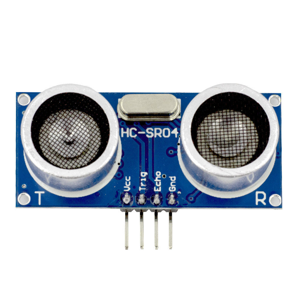
Note the pin labeling, easy!
const int trigPin = 5;
const int echoPin = 18;

#define SOUND_SPEED 0.034

long duration;
float distance;

void setup() {
  Serial.begin(9600);

  pinMode(trigPin, OUTPUT);
  pinMode(echoPin, INPUT);
}

void loop() {
    digitalWrite(trigPin, LOW);
    delayMicroseconds(2);
    digitalWrite(trigPin, HIGH);
    delayMicroseconds(10);
    digitalWrite(trigPin, LOW);

    duration = pulseIn(echoPin, HIGH);
    distance = duration * SOUND_SPEED/2;

    Serial.println(distance);

    delay(50);
}
Read about pulseIn().
Arduino Libraries
Let’s look at how to install a sensor library.
We’ll only do one example, but it works pretty much the same for all others.
DHT22
The DHT22 (and DHT11) used to be pretty popular temperature and humidity sensors. They’re a bit old-fashioned now but still work fine for our purposes.
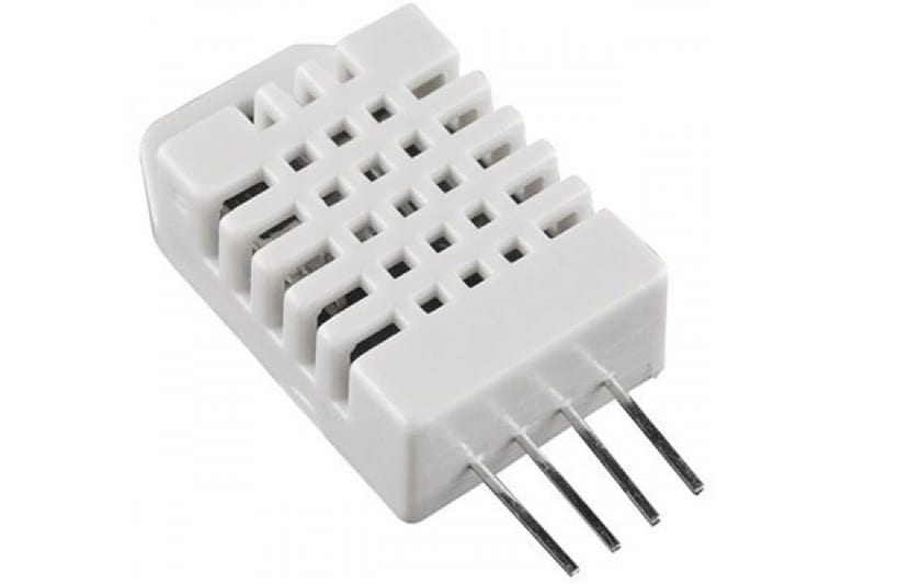
(If you want a more up-to-date sensor the go-to would be the BME280, including air pressure and altitude!)
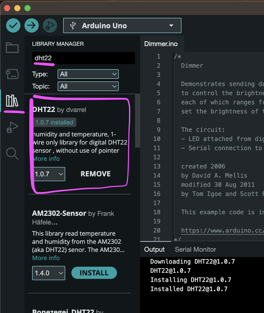
Installing a library
Since Arduino IDE 2.x the library manager sits neatly on the left side of the window.
Just search for DHT22 and install the first result.
Examples
The Ardunio IDE comes with lots of examples and libraries usually add more.
(Sorry for making you type so much code until now!)
Open
File > Examples > DHT22 > dht22test
adjust the pin and flash it!
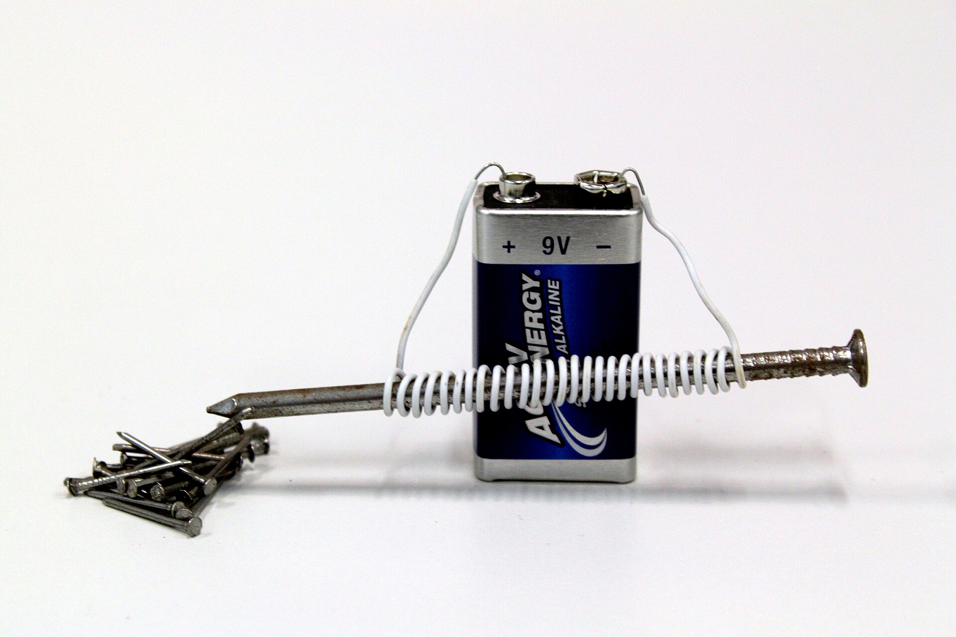
Electro-magentism
Another fun property of electricity: magentism!
If you send electricity through a conductive cable, it naturally becomes a tiny bit magnetic.
You wouldn’t notice though, the effect is very weak.
To enhance it and make the magnet usable, we wind the cable around a metal (usually iron) core (aka a coil).
And boom: electro-magnet!
I’m not going into details about electromagnetism here, but feel free to read up on it.
Electromagnets are used in various applications. We’ll see them being used in motors.
Motors
There are various kinds of motors out there. We’ll start simple and work towards more complex.
DC-motors
DC-motors are the simplest motor.
The name comes from the DC current (the one we’ve been using in our circuits the whole time).
Internally they’re basically an electromagnet that rotates a shaft through alternating between magnetic poles.
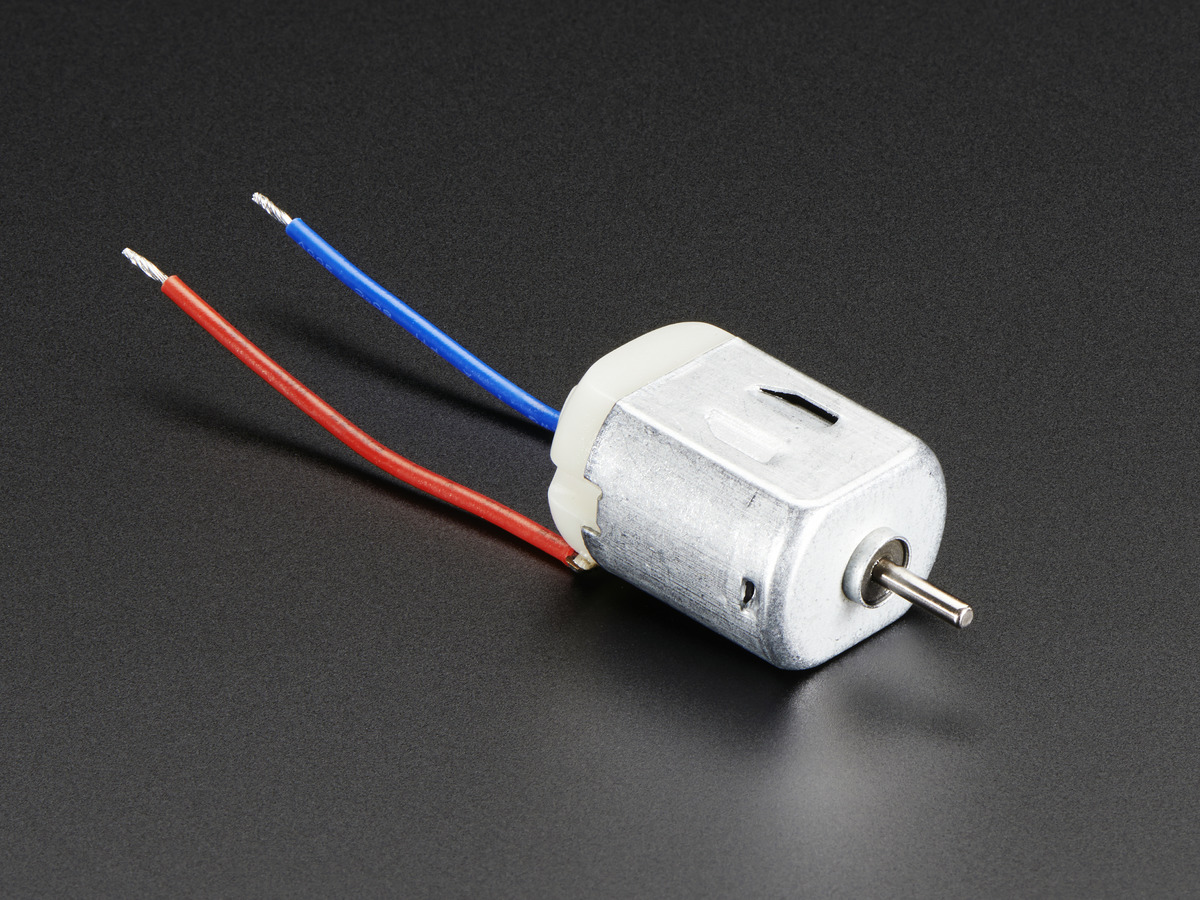
The DC-motor doesn’t care about direction of current.
It does however effect the direction of the rotation!
DC-motors usually run on a high voltage.
3.3V should be enough to get a small one to rotate, but less probably not.
The higher the voltage the faster your motor is rotating.
Most of the time you’ll have a 9V or 12V motor doing some heavy-lifting. For this you’d need a different circuit with a stronger power supply, but sharing the same ground as the rest. And a motor driver (or T-bridge) but this is out of the scope for this workshop.
But it’s also not super hard, just search for it.
The fun part with DC-motors start when you attach cogs and wheels to get different kinds of mechanical motion.
Which brings us to Servo-motors.
Servo motors
Servos are small motors where you can control the angle of the rotation.
In the DC-motor we didn’t have control over the rotation, we could just turn it on and off.
A servo comes with an IC and some mechanical parts that translate a PWM-signal into a rotational angle. Pretty nifty!
Most servos can only rotate on a 180 degree angle however. (There are also 360 degree ones now, but that’s not the standard).

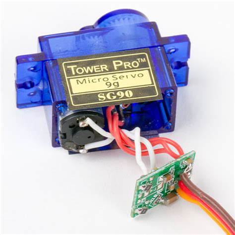
The servo has three pins, GND (brown), VCC (red) and the data pin (yellow-ish).
A circuit is pretty simple then, connect the power and analogWrite() to the data pin!
The Arduino IDE comes with a Servo library preinstalled. We can use it and conveniently give the servo an angle to rotate to instead of interpolating ourselves.
Look at the example at
File > Examples > Servo > Sweep
Here is a cool project by former CTechies using a bunch of servos
https://vimeo.com/718211161
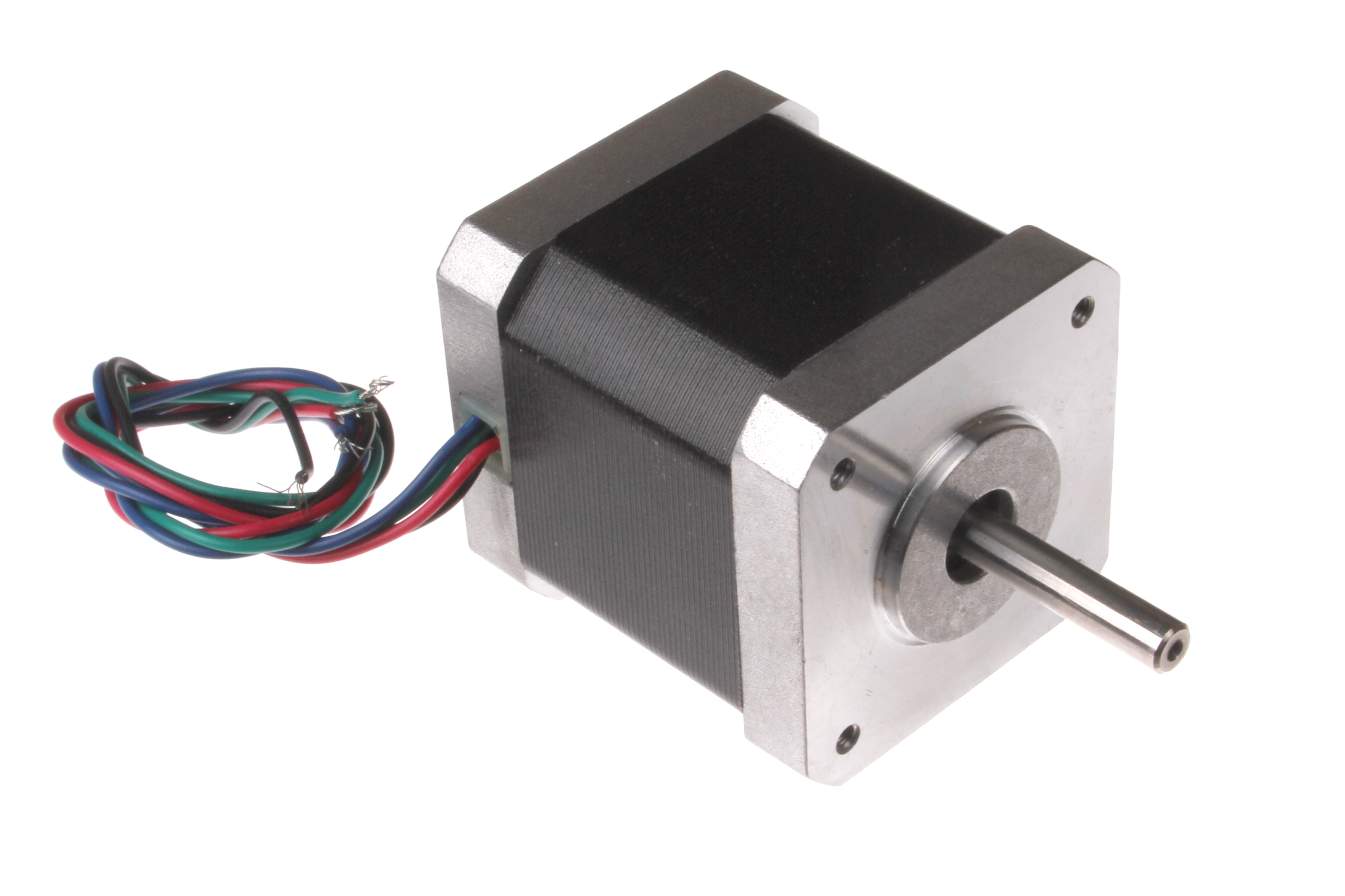
Stepper motors
Steppers give you ultimate control over how many “steps” the motor rotates into one or the other direction.
How many steps a given motor can do is noted in its data sheet.
Steppers are used in pen plotters, 3D printers and generally where you have to move precisely on an axis.
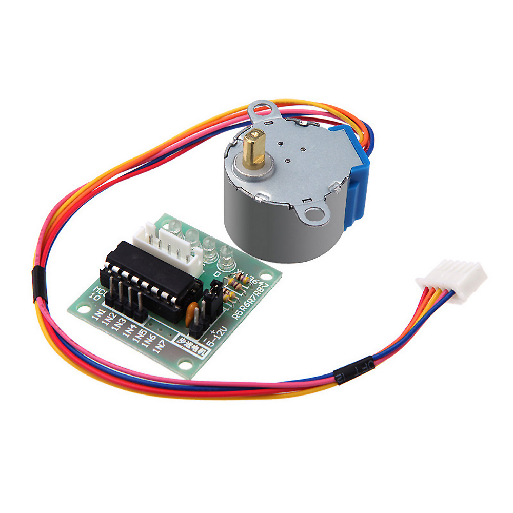
Wiring and controlling a stepper is a tiny bit more advanced and we’re running out of time.
That’s why we leave it at that.
As usual though, the internet is your fiend.
ESP 32
A popular micro-controller and follow-up model of the ESP8266, is the ESP32.
The ESP8266 was the first affordable micro-controller with on-board wifi-chip and networking stack, kind of said to have kick-started the IoT-era.
The ESP32 is bascially the same but faster, more powerful, with Bluetooth and more pins. The total package!
Pinout
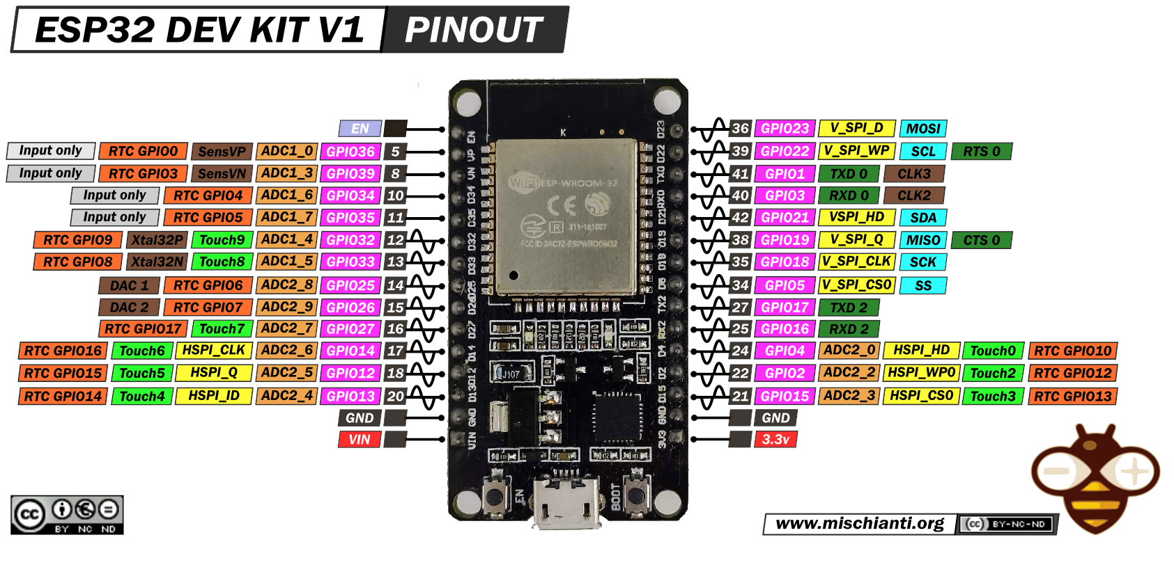
Some things to note are:
-
everything is 3.3V (no 5V available)
-
all pins are PWM
-
pins marked as ADC are analog-digital-converters, DAC are digital-analog-converters
-
pins marked at touch have build-in capacitive sensing
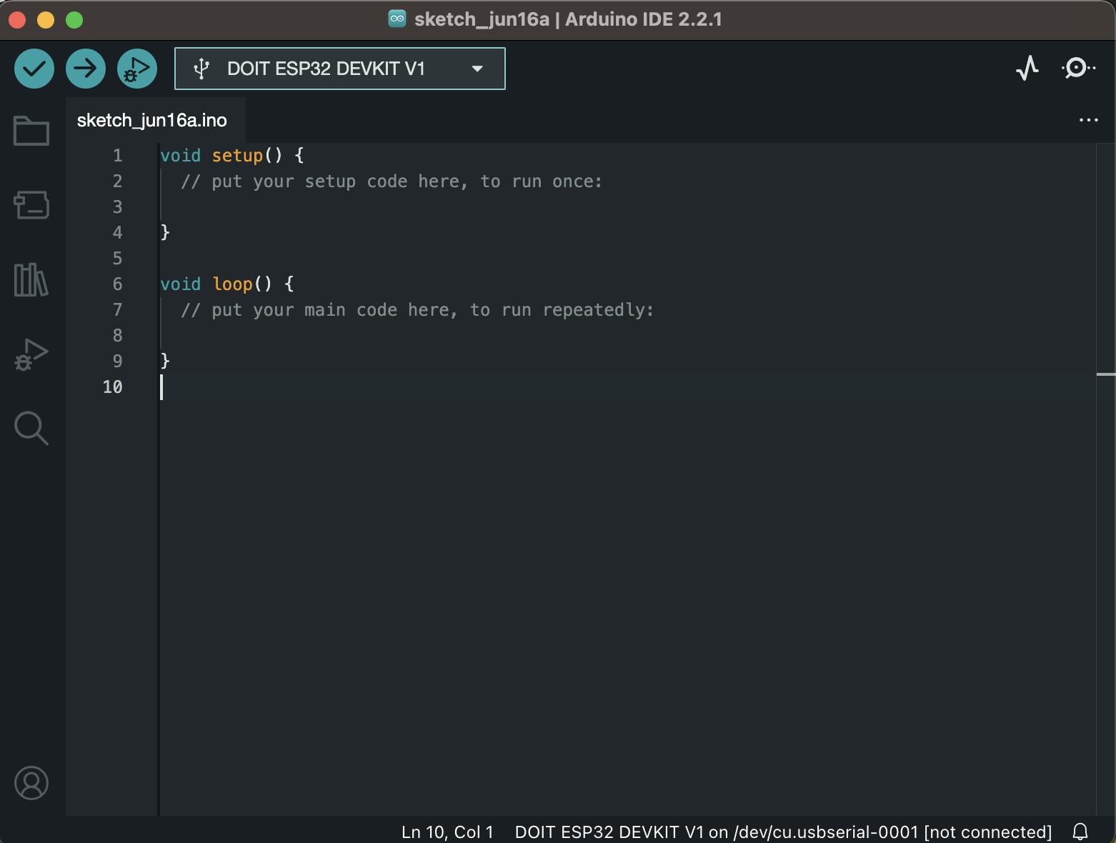
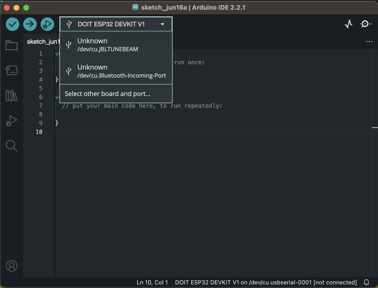
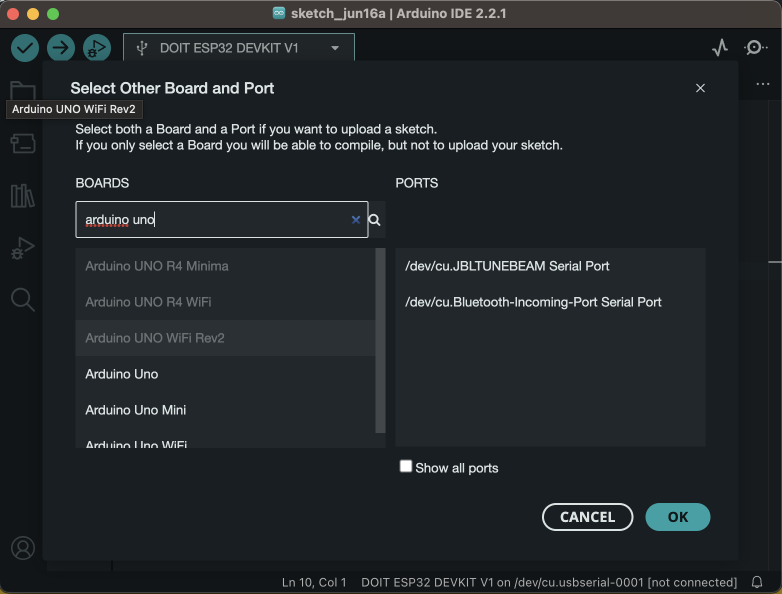
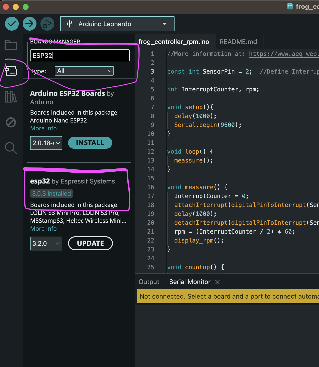
Adding ESP to the IDE
Uploading a hello-world-sketch!
#define LED 2

void setup() {
  Serial.begin(115200);
  pinMode(LED, OUTPUT);
}

void loop() {
  digitalWrite(LED, HIGH);
  Serial.println("LED is on");
  delay(1000);
  digitalWrite(LED, LOW);
  Serial.println("LED is off");
  delay(1000);
}
Note that some ESP32 development boards don’t go into flashing/uploading mode automatically when uploading a new code and you’ll see a lot of dots on the debugging window followed by an error message. If that’s the case, you need to press the ESP32 BOOT button when you start seeing the dots on the debugging window.
We’re ready to go!
Webserver
One cool feature is that the ESP32 can be used as a small webserver, exposing the data it’s dealing with directly to a web interface (in the same network ((or as its own access point)).
This can be useful for configuring your setup without having to connect to the controller directly, or interacting with your piece remotely.
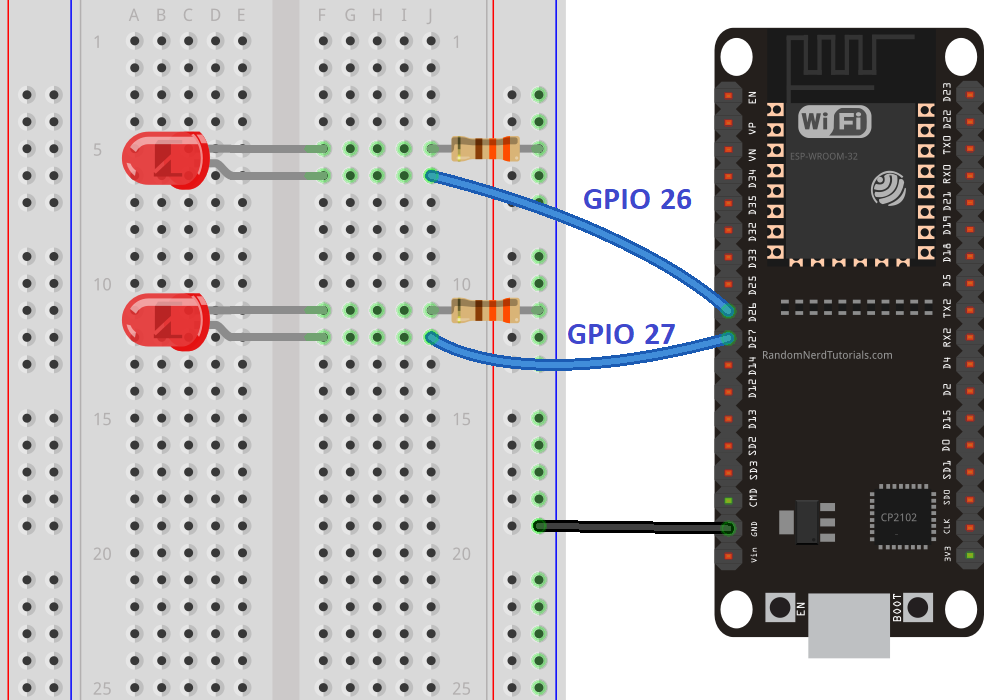
Let’s build the LED ciruit first!
- 2 LEDs
- 2 330 Ohm resistors
- cables and a breadboard
Next we need code to connect the ESP to our local network.
Copy or download the code from here!
We’ll walk through it!
It’s useful to understand:
-
Client-Server architecture
-
Basic TCP/IP
-
HTTP as a protocol and markup language
Try out your app!
Instead of displaying the info on an HTML page, we can write it as JSON or just plain text.
Here is a stripped down version of the sketch above that just returns a plain text string.
Of course everything is a bit nicer with JSON! The popular Arduino_JSON has you covered! I leave it as an exercise to interested readers to install this library and look through the examples.
Strictly, there is no need for HTTP. Do whatever you feel comfortable with or what gets your project up and running the fastest!
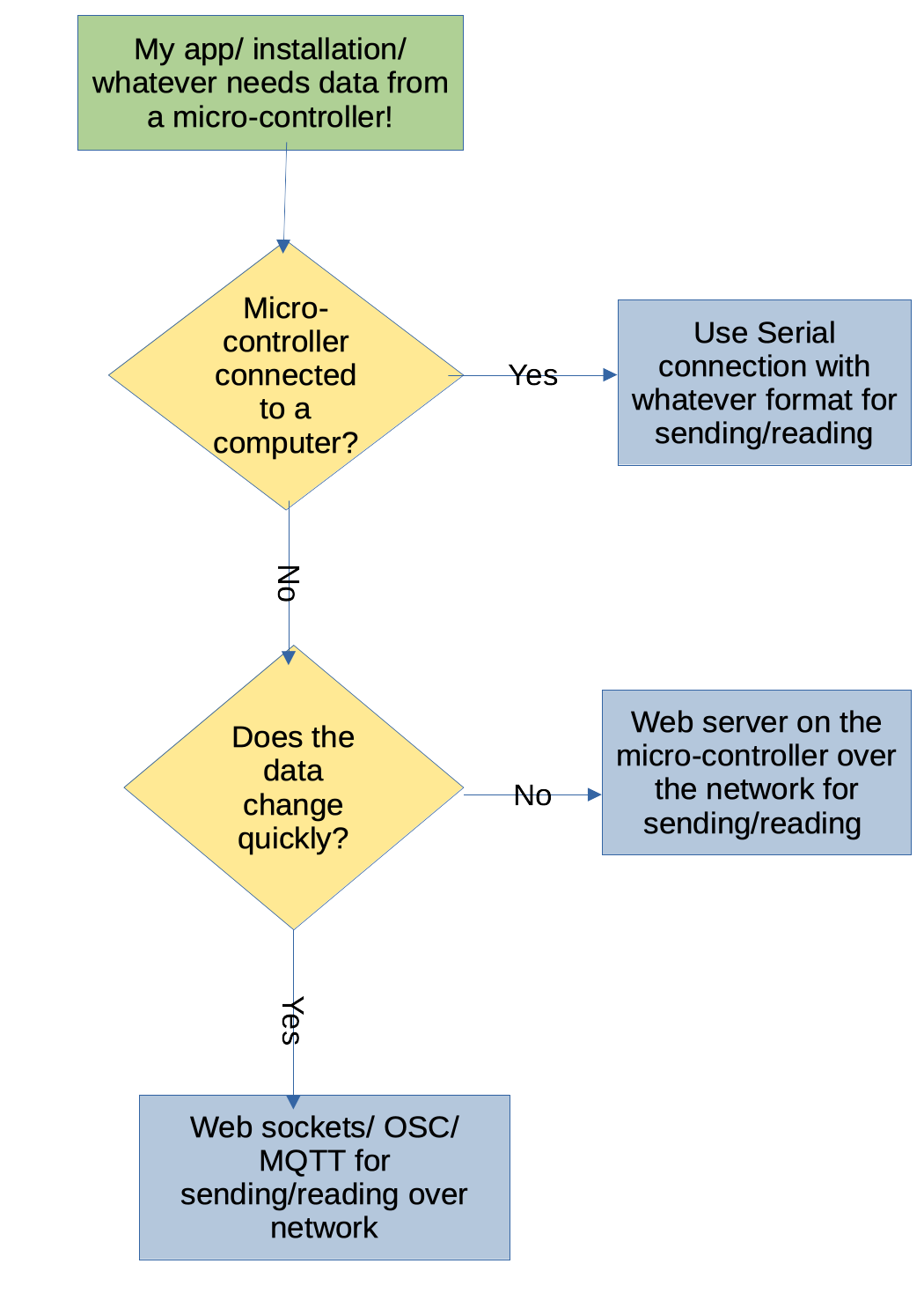
Usually these questions will get to which approach to use:
-
“Just” reading data? Or also sending data?
-
How fast does the data change? Is polling/ requesting enough? Do we need to send out constantly?
I made a handy flowchart for my own personal opinion on when to use what.
OSC
OSC stands for Open Sound Control and is the successor protocol to MIDI.
It’s a widely popular real-time protocol in the event, music and creative tech scene and great for communicating between different programs on the same computer or on different computers. And it’s easy to use! All our dreams come true!
OSC words
There is some lingo in the OSC world:
- Stream: The communication channel between Client and Server. Where messages are passed
- Message: the smallest unit of OSC data
- Bundle: mutliple messages to be excuted by the server at the same time
The stream can be implemented using different transport layer protocols, but we don’t have to care about that.

Maybe you’ve noticed the OSC address scheme looks very much like the web url address scheme. Coincident? Who knows?! (I really don’t know, look it up and tell me)
There are multiple libraries implementing OSC for Arduino/ESP, we’ll be using OSC by Adrian Freed (who also co-wrote the standard).
Go ahead and download it via the Arduino IDE’s package manager.
Example time!
Open up the OSC/ESP8266sendMessage example.
Let’s look throught the code. What is familiar from the web server example? What is different?
Just enough networking to get by
What are UDP, IP and port?
Exercise time
Adjust the code in the example and have some networking fun!
First part
-
Change the message “hello, osc.” and address “/hello” to something that makes sense in the context of your measurements/ circuit/ project. Also adjust the IP and ports once you know them
-
Figure out your own computer’s IP address in our local network
-
Do you have a programm that can read OSC from the network? If not I have a PureData patch and a Godot Project prepared for this in the “Your environment” section. (Feel free to send me patches, sketches, sessions and projects from your favourite tool for the collection)
-
Flash the board and read the incoming messages!
Second part
Since we’re all in the same network, we can send and read each other’s messages.
Get together in groups and change your setups to send, receive and control various parts from various micro-controllers and computers!
Optional
What we didn’t do, but what you can check out:
-
We only send from the ESP, but we can also receive it. Look at the provided example and adjust it, you should know all the relevant steps by now!
-
You can in fact also talk OSC over a serial connection (because OSC abstracts the transport away!) There is an example for that, too!
NodeJS
NodeJS is server-side JavaScript. You can write your own programs and put them on a server to be reachable throught the internet!
Reading OSC
There are many Node modules that deal with OSC, we’ll be using node-osc by MylesBorins but feel free to explore different options.
You can find a small example project in environments/nodejs/
openFrameworks
Reading OSC
Open the example project in environments/of/ofOsc/ and build it.
Godot
Godot is an open source 2D and 3D game engine.
https://godotengine.org/
Reading OSC
@tbd
PureData
PureData (or just Pd) is an open source visual programming language for multimedia.
https://puredata.info/
Reading OSC
Based on this tutorial
https://simonhutchinson.com/2022/02/07/open-sound-control-osc-in-pure-data-vanilla/
You can find the patch in environments/pd/osc-example.pd
LED stripes
There’s a variety of LED stripes out there, but the company Adafruit made a special one called the Neopixel where we can control every pixel individually! Nice!
Original Neopixels are fairly expensive but there are a bunch that are compatible with the original library from Adafruit like the WS2812b.
The stripes come in various “densities”, as in, how many pixels per 30cm strip. While very dense pixels might look cool, I’d usually prefer ones with a little more spacing, so we can cut and solder custom lengths.
Cut and solder? Yes! The stripes usually expose their connections and you can just cut them with wire clippers and solder them back together, or extend them with cables or whatever you need to do. Just make sure the direction stays the same! The GND, VCC and data connectors have to match!
Install the library
![]()
In the Arduino IDE, click on the library manager on the left and search for “neopixel”. The “Adafruit Neopixel by Adafruit” is what we want. There are different others available, too. For for us the simple one is enough.
Open the simple example
Under File > Examples > Adafruit Neopixel > open the simple example. To connect you just have to connect VCC, GND and one data pin (adjust on line 10).
Adjust the number of LEDs you want to light up (NUMPIXELS on line 14). And then try to run the code!
There specified number of pixels should light up in one color. Look at the code in the loop.
It’s very similar to working with canvases in P5.js. Clear the pixels, set a color in RGB and call show to actually send the color data to the stripe!
[Circuit] Photoresistor and led stripe
Let’s combine input and output!
Wire up a photoresistor and LED stripe like in the diagram. You also need one resitor of at least 1k.
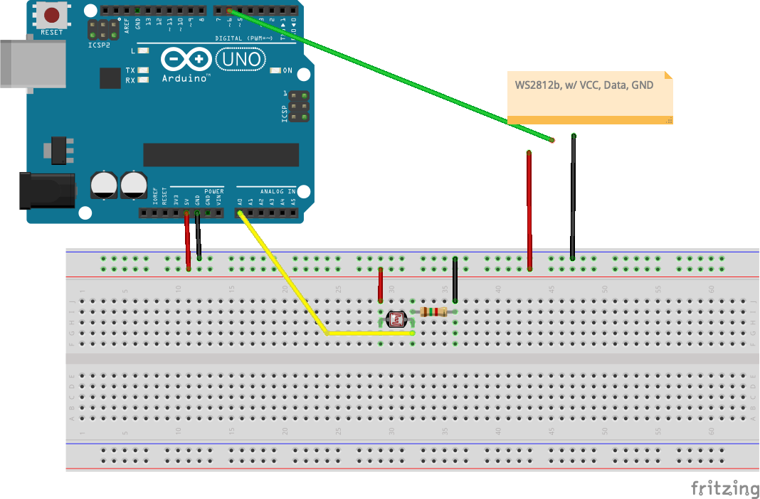
Use and adjust the code. In the example the reading from the resistor is used in mboth the brightness and the color of the LEDs. But you can make your own rules!
How about until a threshold is reached, only the even numbered LEDs light up. And above the threshold only the odd numbers?
#include <Adafruit_NeoPixel.h>

#define PIN 6
#define NUMPIXELS 30
Adafruit_NeoPixel pixels(NUMPIXELS, PIN, NEO_GRB + NEO_KHZ800);

const int photoresistor = A0;

void setup() {
  pixels.begin();
  Serial.begin(9600);
  pinMode(photoresistor, INPUT);
}

void loop() {
  int reading = analogRead(photoresistor);
  Serial.print(reading);
  Serial.print(" ");

  // mapping based on my current readings, please adjust accordingly!
  int brightness = map(reading, 800, 1010, 50, 180);
  Serial.println(brightness);

  pixels.clear();
  pixels.setBrightness(brightness);

  for(int i=0; i<NUMPIXELS; i++) {
    pixels.setPixelColor(i, pixels.Color(brightness, 0, 250 - brightness));
  }
  pixels.show();
  delay(200);
}
Building a MIDI controller
Can we build our own midi controllers with an Arduino? Yes!
I recommend using the Arduino Leonardo (or similar), as it already registers as USB device when you plug it in. Also useful for making custom game controllers.
The library to use to actually announce the Leonardo as a MIDI device is called MIDIUSB (straightforward naming) and the library control surface by Pieter P kind of does the DAW mappings.
This video gives a short intro to the Leonardo and the library and testing a custom midi controller https://www.youtube.com/watch?v=WRz6JKeXZgk (it’s not the highest quality video, sorry about that).
NOTE: In past workshops only Logic and Ableton recognized the custom MIDI controller. ProTools kind of saw it but didn’t accept input, sadly.
You can use a fader or a poti for this!
Making a synthesizer
With the power of PWM we can output an audio signal directly to a ~pin. And then connect that to headphones or speakers or something.
Instead of using the limited tone() function, we can code our own wave and modulate it! Proper synthesis! It’s still very low-fi, the Uno has 8bit depth, but it works!
There is various tutorials out there but I recommend this one by Peter Knight
also because so many people have tried and improved on it
I’ll post Peter’s code here, because who knows for how much longer Google Code Archive will exist
// Auduino, the Lo-Fi granular synthesiser
//
// by Peter Knight, Tinker.it http://tinker.it
//
// Help:      http://code.google.com/p/tinkerit/wiki/Auduino
// More help: http://groups.google.com/group/auduino
//
// Analog in 0: Grain 1 pitch
// Analog in 1: Grain 2 decay
// Analog in 2: Grain 1 decay
// Analog in 3: Grain 2 pitch
// Analog in 4: Grain repetition frequency
//
// Digital 3: Audio out (Digital 11 on ATmega8)
//
// Changelog:
// 19 Nov 2008: Added support for ATmega8 boards
// 21 Mar 2009: Added support for ATmega328 boards
// 7 Apr 2009: Fixed interrupt vector for ATmega328 boards
// 8 Apr 2009: Added support for ATmega1280 boards (Arduino Mega)

#include <avr/io.h>
#include <avr/interrupt.h>

uint16_t syncPhaseAcc;
uint16_t syncPhaseInc;
uint16_t grainPhaseAcc;
uint16_t grainPhaseInc;
uint16_t grainAmp;
uint8_t grainDecay;
uint16_t grain2PhaseAcc;
uint16_t grain2PhaseInc;
uint16_t grain2Amp;
uint8_t grain2Decay;

// Map Analogue channels
#define SYNC_CONTROL         (4)
#define GRAIN_FREQ_CONTROL   (0)
#define GRAIN_DECAY_CONTROL  (2)
#define GRAIN2_FREQ_CONTROL  (3)
#define GRAIN2_DECAY_CONTROL (1)


// Changing these will also requires rewriting audioOn()

#if defined(__AVR_ATmega8__)
//
// On old ATmega8 boards.
//    Output is on pin 11
//
#define LED_PIN       13
#define LED_PORT      PORTB
#define LED_BIT       5
#define PWM_PIN       11
#define PWM_VALUE     OCR2
#define PWM_INTERRUPT TIMER2_OVF_vect
#elif defined(__AVR_ATmega1280__)
//
// On the Arduino Mega
//    Output is on pin 3
//
#define LED_PIN       13
#define LED_PORT      PORTB
#define LED_BIT       7
#define PWM_PIN       3
#define PWM_VALUE     OCR3C
#define PWM_INTERRUPT TIMER3_OVF_vect
#else
//
// For modern ATmega168 and ATmega328 boards
//    Output is on pin 3
//
#define PWM_PIN       3
#define PWM_VALUE     OCR2B
#define LED_PIN       13
#define LED_PORT      PORTB
#define LED_BIT       5
#define PWM_INTERRUPT TIMER2_OVF_vect
#endif

// Smooth logarithmic mapping
//
uint16_t antilogTable[] = {
  64830,64132,63441,62757,62081,61413,60751,60097,59449,58809,58176,57549,56929,56316,55709,55109,
  54515,53928,53347,52773,52204,51642,51085,50535,49991,49452,48920,48393,47871,47356,46846,46341,
  45842,45348,44859,44376,43898,43425,42958,42495,42037,41584,41136,40693,40255,39821,39392,38968,
  38548,38133,37722,37316,36914,36516,36123,35734,35349,34968,34591,34219,33850,33486,33125,32768
};
uint16_t mapPhaseInc(uint16_t input) {
  return (antilogTable[input & 0x3f]) >> (input >> 6);
}

// Stepped chromatic mapping
//
uint16_t midiTable[] = {
  17,18,19,20,22,23,24,26,27,29,31,32,34,36,38,41,43,46,48,51,54,58,61,65,69,73,
  77,82,86,92,97,103,109,115,122,129,137,145,154,163,173,183,194,206,218,231,
  244,259,274,291,308,326,346,366,388,411,435,461,489,518,549,581,616,652,691,
  732,776,822,871,923,978,1036,1097,1163,1232,1305,1383,1465,1552,1644,1742,
  1845,1955,2071,2195,2325,2463,2610,2765,2930,3104,3288,3484,3691,3910,4143,
  4389,4650,4927,5220,5530,5859,6207,6577,6968,7382,7821,8286,8779,9301,9854,
  10440,11060,11718,12415,13153,13935,14764,15642,16572,17557,18601,19708,20879,
  22121,23436,24830,26306
};
uint16_t mapMidi(uint16_t input) {
  return (midiTable[(1023-input) >> 3]);
}

// Stepped Pentatonic mapping
//
uint16_t pentatonicTable[54] = {
  0,19,22,26,29,32,38,43,51,58,65,77,86,103,115,129,154,173,206,231,259,308,346,
  411,461,518,616,691,822,923,1036,1232,1383,1644,1845,2071,2463,2765,3288,
  3691,4143,4927,5530,6577,7382,8286,9854,11060,13153,14764,16572,19708,22121,26306
};

uint16_t mapPentatonic(uint16_t input) {
  uint8_t value = (1023-input) / (1024/53);
  return (pentatonicTable[value]);
}


void audioOn() {
#if defined(__AVR_ATmega8__)
  // ATmega8 has different registers
  TCCR2 = _BV(WGM20) | _BV(COM21) | _BV(CS20);
  TIMSK = _BV(TOIE2);
#elif defined(__AVR_ATmega1280__)
  TCCR3A = _BV(COM3C1) | _BV(WGM30);
  TCCR3B = _BV(CS30);
  TIMSK3 = _BV(TOIE3);
#else
  // Set up PWM to 31.25kHz, phase accurate
  TCCR2A = _BV(COM2B1) | _BV(WGM20);
  TCCR2B = _BV(CS20);
  TIMSK2 = _BV(TOIE2);
#endif
}


void setup() {
  pinMode(PWM_PIN,OUTPUT);
  audioOn();
  pinMode(LED_PIN,OUTPUT);
}

void loop() {
  // The loop is pretty simple - it just updates the parameters for the oscillators.
  //
  // Avoid using any functions that make extensive use of interrupts, or turn interrupts off.
  // They will cause clicks and poops in the audio.

  // Smooth frequency mapping
  //syncPhaseInc = mapPhaseInc(analogRead(SYNC_CONTROL)) / 4;

  // Stepped mapping to MIDI notes: C, Db, D, Eb, E, F...
  //syncPhaseInc = mapMidi(analogRead(SYNC_CONTROL));

  // Stepped pentatonic mapping: D, E, G, A, B
  syncPhaseInc = mapPentatonic(analogRead(SYNC_CONTROL));

  grainPhaseInc  = mapPhaseInc(analogRead(GRAIN_FREQ_CONTROL)) / 2;
  grainDecay     = analogRead(GRAIN_DECAY_CONTROL) / 8;
  grain2PhaseInc = mapPhaseInc(analogRead(GRAIN2_FREQ_CONTROL)) / 2;
  grain2Decay    = analogRead(GRAIN2_DECAY_CONTROL) / 4;
}

SIGNAL(PWM_INTERRUPT)
{
  uint8_t value;
  uint16_t output;

  syncPhaseAcc += syncPhaseInc;
  if (syncPhaseAcc < syncPhaseInc) {
    // Time to start the next grain
    grainPhaseAcc = 0;
    grainAmp = 0x7fff;
    grain2PhaseAcc = 0;
    grain2Amp = 0x7fff;
    LED_PORT ^= 1 << LED_BIT; // Faster than using digitalWrite
  }

  // Increment the phase of the grain oscillators
  grainPhaseAcc += grainPhaseInc;
  grain2PhaseAcc += grain2PhaseInc;

  // Convert phase into a triangle wave
  value = (grainPhaseAcc >> 7) & 0xff;
  if (grainPhaseAcc & 0x8000) value = ~value;
  // Multiply by current grain amplitude to get sample
  output = value * (grainAmp >> 8);

  // Repeat for second grain
  value = (grain2PhaseAcc >> 7) & 0xff;
  if (grain2PhaseAcc & 0x8000) value = ~value;
  output += value * (grain2Amp >> 8);

  // Make the grain amplitudes decay by a factor every sample (exponential decay)
  grainAmp -= (grainAmp >> 8) * grainDecay;
  grain2Amp -= (grain2Amp >> 8) * grain2Decay;

  // Scale output to the available range, clipping if necessary
  output >>= 9;
  if (output > 255) output = 255;

  // Output to PWM (this is faster than using analogWrite)
  PWM_VALUE = output;
}
Control a synth in PureData
Resources
Shops
Shops I’ve bought from in the past:
- https://www.berrybase.de/
- https://www.roboter-bausatz.de/
- https://www.makershop.de/
- https://www.pollin.de/
- https://tweakable-parts.com/en/
Also just ebay and alibaba if you have the time to wait for shipment from China.
It’s also always worth to ask a nerd friend for unused stuff!